Three Joint Robotic Arm
This is a three-joint robotic arm controlled by the Joystick. The Joystick can control the robot to move forward, backward, clockwise, and counterclockwise, and move the claws open and close. The servos in the robot work as the joints of the robot.
| Engineer | School | Area of Interest | Grade |
|---|---|---|---|
| Bella P | Valley Christian High School | Electrical Engineering | Incoming Sophomore |

Modification
.
Modification Milestone
I created a smartphone app to control the robot arm as part of my modification. Prior to this, I could only control the robot using a joystick. However, after reaching a milestone, I was able to use a single code through the smartphone app to control the robot. I developed the app using the MIT App Inventor. Initially, I designed a joystick controller app which had the joystick in the middle to control the robot. However, the joystick app caused the Bluetooth to disconnect and prevented the robot from functioning properly. As a solution, I created a button app with a total of eight buttons, each controlling a specific servo. After creating a block code using the MIT App Inventor, I developed two different Arduino codes, one for Bluetooth and the other for the joystick controller. I then combined the two codes to enable both the joystick and the button app to work using a single code. Following troubleshooting, I successfully managed to control the robot using both the button app and the joystick simultaneously.
Final Smartphone App

- Figure 1 Robot control smartphone app
Blockcode
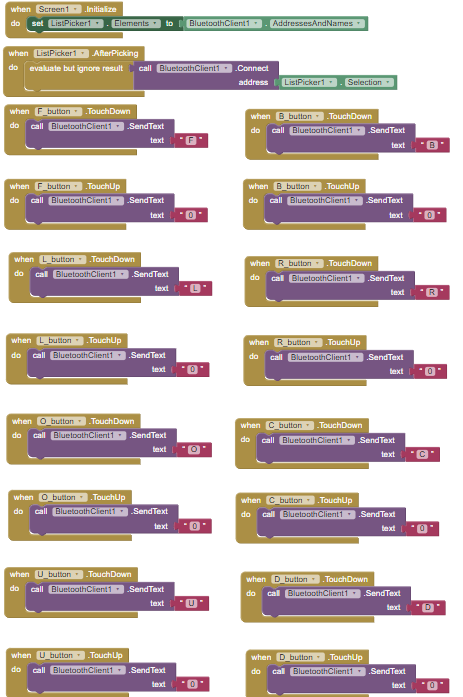
-
Figure 2 Blockcode for the smartphone app
Code
Arduino code for the smartphone controlled robot
#include "SoftwareSerial.h"
#include <Servo.h>

SoftwareSerial bt(2,10);

int input;

Servo rotation; // pin 4 (left, right) (LR)
Servo lower; // pin 5 (forward, backward) (FB)
Servo upper; // pin 6 (forward, backward but on top) (UD for up down)
Servo claw; // pin 7 (open, close) (OC)

int rotation_pos = 90;
int lower_pos = 90;
int upper_pos = 90;
int claw_pos = 90;

void setup() {
  // put your setup code here, to run once:
  Serial.begin(9600);
  bt.begin(9600);

  rotation.attach(4);
  lower.attach(5);
  upper.attach(6);
  claw.attach(7);

  rotation.write(rotation_pos);
  lower.write(lower_pos);
  upper.write(upper_pos);
  claw.write(claw_pos);
}

void loop() {
  // put your main code here, to run repeatedly:
  // testing maximum servo rotation
  /*
  for (int i = 0; i < 180; i++) {
    rotation.write(i);
    delay(50);
  }
  for (int i = 180; i > 0; i--) {
    rotation.write(i);
    delay(50);
  }
  delay(50);
  */

  if(bt.available()) {
    input = bt.read();
    Serial.write(input);
    Serial.println();
    // LR is rotation servo
    if (input == 'L') {
      rotation_pos += 15;
      if (rotation_pos > 180) {
        rotation_pos = 180;
      }
      rotation.write(rotation_pos);
      Serial.println("rotation moved to: ");
      Serial.print(rotation_pos);
      Serial.println();
    }
    else if (input == 'R') {
      rotation_pos -= 15;
      if (rotation_pos < 0) {
        rotation_pos = 0;
      }
      rotation.write(rotation_pos);
      Serial.println("rotation moved to: ");
      Serial.print(rotation_pos);
      Serial.println();
    }
    // FB is lower servo
    else if (input == 'F') {
      lower_pos += 15;
      // changed lower_pos max to 135 (any more and it crushes the cables / also don't want to break bottom servo cables)
      if (lower_pos > 135) {
        lower_pos = 135;
      }
      lower.write(lower_pos);
      Serial.println("lower arm moved to: ");
      Serial.print(lower_pos);
      Serial.println();
    }
    else if (input == 'B') {
      lower_pos -= 15;
      if (lower_pos < 0) {
        lower_pos = 0;
      }
      lower.write(lower_pos);
      Serial.println("lower arm moved to: ");
      Serial.print(lower_pos);
      Serial.println();
    }
    // OC is claw servo
    else if (input == 'O') {
      claw_pos += 15;
      if (claw_pos > 165) {
        claw_pos = 165;
      }
      claw.write(claw_pos);
      Serial.println("claw moved to: ");
      Serial.print(claw_pos);
      Serial.println();
    }
    else if (input == 'C') {
      claw_pos -= 15;
      if (claw_pos < 0) {
        claw_pos = 0;
      }
      claw.write(claw_pos);
      Serial.println("claw moved to: ");
      Serial.print(claw_pos);
      Serial.println();
    }
    // UD is upper servo
    else if (input == 'U') {
      upper_pos += 15;
      if (upper_pos > 180) {
        upper_pos = 180;
      }
      upper.write(upper_pos);
      Serial.println("upper arm moved to: ");
      Serial.print(upper_pos);
      Serial.println();
    }
    else if (input == 'D') {
      upper_pos -= 15;
      if (upper_pos < 0) {
        upper_pos = 0;
      }
      upper.write(upper_pos);
      Serial.println("upper arm moved to: ");
      Serial.print(upper_pos);
      Serial.println();
    }
    else {
      // do nothing
      // this isn't needed but looks neater
    }
  }
}
Challenge
While making modifications, I faced a few challenges. Initially, the Bluetooth module and the Arduino code couldn’t communicate. After troubleshooting, I discovered that the battery didn’t provide enough power for the Bluetooth module. Additionally, I encountered issues with the Bluetooth and the app disconnecting after creating the joystick smartphone app. Finally, coding was a significant challenge in this modification because it involved various new concepts, and I hadn’t yet learned how to merge two different codes. However, with the help of instructors, I successfully created a code that could control both the joystick and the Bluetooth simultaneously.
Final Milestone
For my final milestone, I completed the Three Joint Robotic Arm. To finish the project, I finished connecting the wire to the Joystick. Also, I wired the servos to the nano bo. The Joystick is connected to the nano board and controls the Robot arm. Each direction has its function. Direction 1 makes the robot lean forward. Direction 2 makes the robot lean backward. Direction 3 makes the robot spin counterclockwise. Direction 4 makes the robot spin clockwise. Direction 5 makes the robot arm’s claw close. Direction 6 makes the robot arm’s claw to open. Direction 7 makes the robot record the action. The program inside the robot arm allows the robot arm to record up to 10 actions. The buzzer will sound once, and then it will record ten actions repeatedly. After ten actions are completed, the buzzer will sound again. Lastly, Direction 8 makes the robot arm perform recorded actions. The buzzer will sound, and the robot will perform the recorded action; after the action is completed, the buzzer will sound again. I faced some challenges when I connected the servo wires. I did not realize that the wires would be matched when connected to the nano board by order of grond-power-controller. But after connecting the wire with the matched spot. The code worked. Throughout this project, I was able to learn about the basics of coding through testing the Arduino, nano shield, Joystick, servos, and more. I was able to acquire basic knowledge of engineering by assembling the robot arm. I hope to learn more detailed coding after BSE and have the opportunity to engineer more advanced projects.
Second Milestone
For my second milestone, I tested the Joystick module, tested the servo, and assembled my robot arm. When testing the servo, I made the servo move as the output of my code. The input was the number, and the servo would move depending on the number I input. When I put 1 as the input, the servo moves to an angle of 10°, and if 2, it moves to 20°, 3 to 60°, 4 to 80°, 5 to 100°, 6 to 120°, 7 to 140°, 8 to 160°. The code used the function of loops, enabling it to repeat the specific part of the code until something that makes the loop stop happens. Next, I assembled the robot arm. The servos are used to join the robot. For the next milestone, I will test the robot and test the code for the servos. Also, I will wire the Joystick and the servos to the robot.
First Milestone
In my first milestone, I set up the Arduino and updated the initial sketch to the Nano. The Nano motherboard flashed once every second as the output of the sketch. The first sketch involved digital code, causing the LED to flash every second because digital code only has highs and lows, unlike analog. Next, I tested the Nano shield and encountered some problems. When I entered the code, it didn’t work because the library wasn’t installed on my Arduino, and the code required the library to function. After installing the library, the code started working. For my next milestone, I will focus on testing the Joystick module, testing the servo, and making it move. Additionally, I will work on assembling the robot arm.
Schematics
The wiring diagram for the joystick and the servo
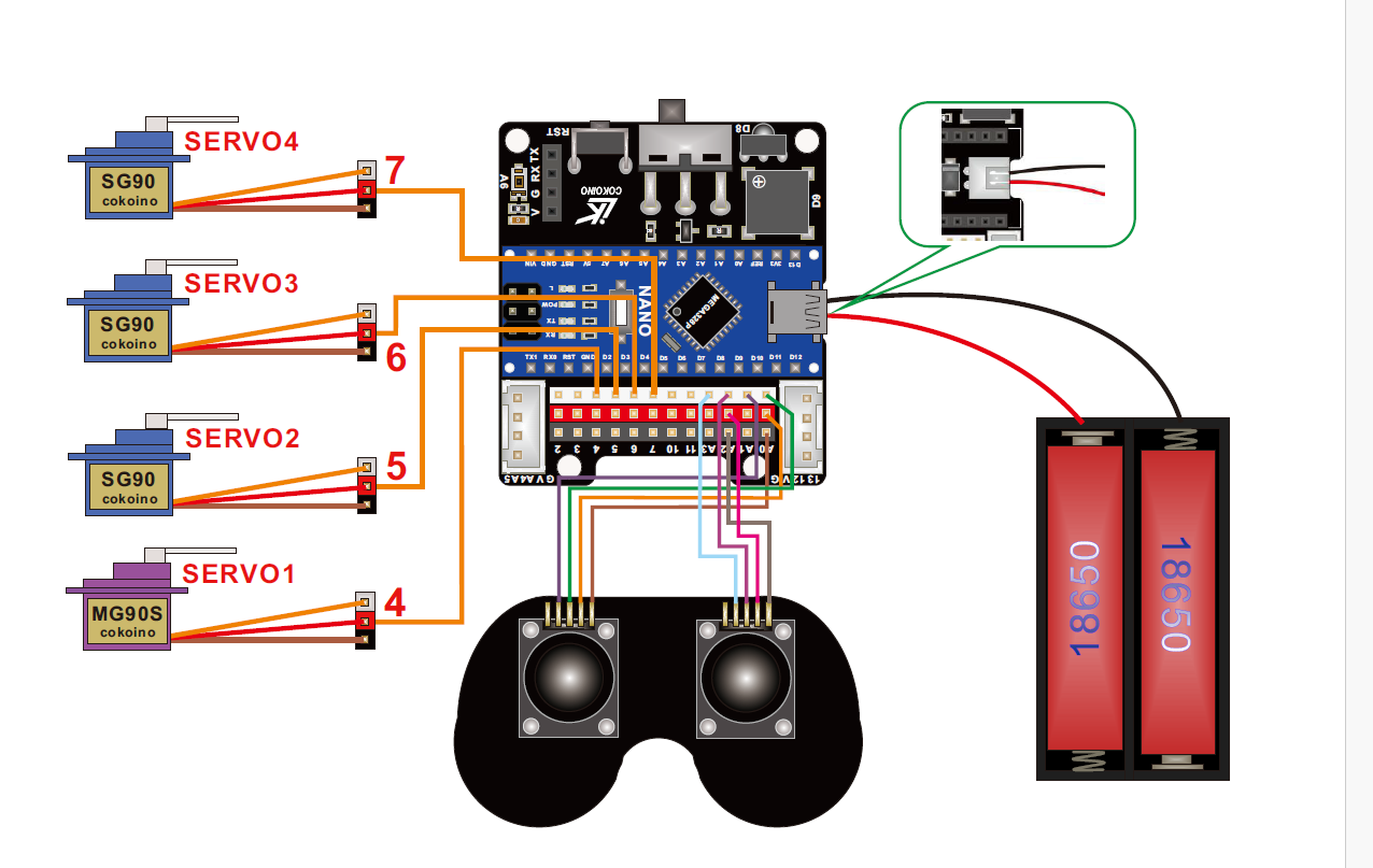
- Figure 3 Robot arm joystick wiring schematics
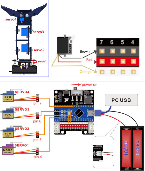
- Figure 4 Robot arm servo wiring schematics
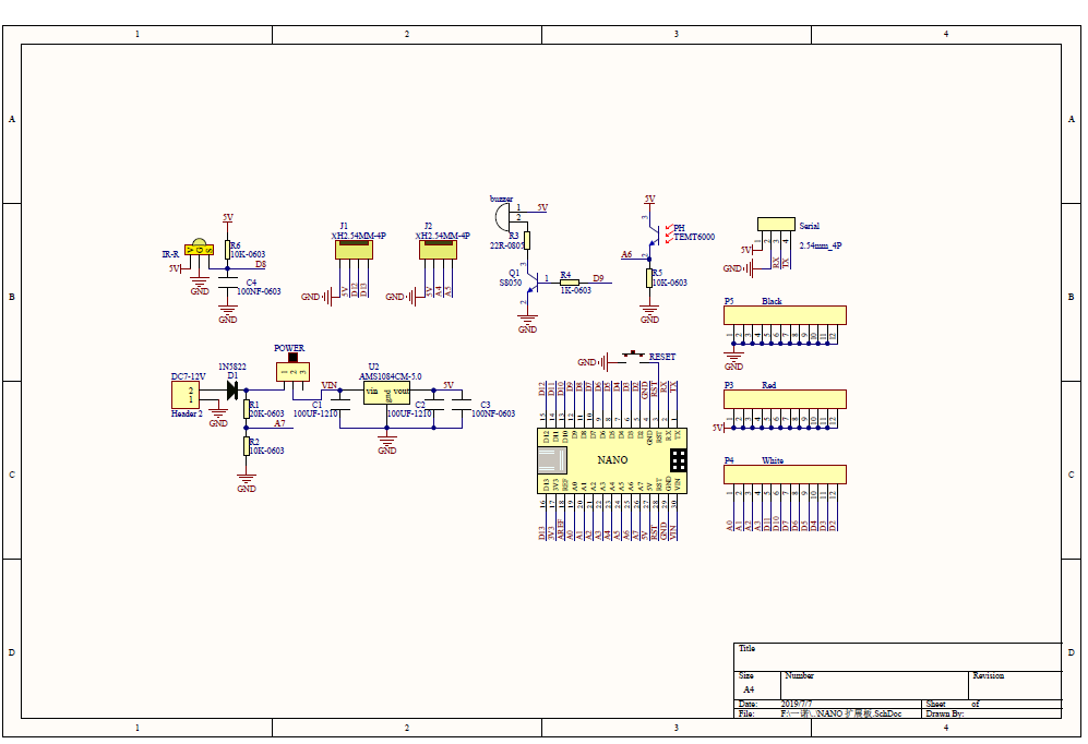
-
Figure 5 The Nano shield schematics
*Three Joint Robot Arm Lesson 3,6,7
Code
/*
 *
 *                                     ________
 *                         ----|servo4|
 *                        |            --------
 *                    |servo3|
 *                        |
 *                        |
 *                    |servo2|
 *                        |
 *                        |
 *                  ___________
 *                  |  servo1 |
 *         ____________________
 *         ____________________
 * Fanctions:
 * arm.servo1.read();   //read the servo of angle
 * arm.servo2.read();
 * arm.servo3.read();
 * arm.servo4.read();
 *
 * arm.servo1.write(angle);   //servo run
 * arm.servo2.write(angle);
 * arm.servo3.write(angle);
 * arm.servo4.write(angle);
 *
 * arm.left(speed);    //perform the action
 * arm.right(speed);
 * arm.up(speed);
 * arm.down(speed);
 * arm.open(speed);
 * arm.close(speed);
 *
 * arm.captureAction();    //capture the current action,return pointer array
 * arm.do_action(int *p,int speed);  //P is a pointer to the array
 *
 * arm.JoyStickL.read_x(); //Returns joystick numerical
 * arm.JoyStickL.read_y();
 * arm.JoyStickR.read_x();
 * arm.JoyStickR.read_y();
 */
#include "src/CokoinoArm.h"
#define buzzerPin 9

CokoinoArm arm;
int xL,yL,xR,yR;

const int act_max=10;    //Default 10 action,4 the Angle of servo
int act[act_max][4];    //Only can change the number of action
int num=0,num_do=0;
///////////////////////////////////////////////////////////////
void turnUD(void){
  if(xL!=512){
    if(0<=xL && xL<=100){arm.up(10);return;}
    if(900<xL && xL<=1024){arm.down(10);return;}
    if(100<xL && xL<=200){arm.up(20);return;}
    if(800<xL && xL<=900){arm.down(20);return;}
    if(200<xL && xL<=300){arm.up(25);return;}
    if(700<xL && xL<=800){arm.down(25);return;}
    if(300<xL && xL<=400){arm.up(30);return;}
    if(600<xL && xL<=700){arm.down(30);return;}
    if(400<xL && xL<=480){arm.up(35);return;}
    if(540<xL && xL<=600){arm.down(35);return;}
    }
}
///////////////////////////////////////////////////////////////
void turnLR(void){
  if(yL!=512){
    if(0<=yL && yL<=100){arm.right(0);return;}
    if(900<yL && yL<=1024){arm.left(0);return;}
    if(100<yL && yL<=200){arm.right(5);return;}
    if(800<yL && yL<=900){arm.left(5);return;}
    if(200<yL && yL<=300){arm.right(10);return;}
    if(700<yL && yL<=800){arm.left(10);return;}
    if(300<yL && yL<=400){arm.right(15);return;}
    if(600<yL && yL<=700){arm.left(15);return;}
    if(400<yL && yL<=480){arm.right(20);return;}
    if(540<yL && yL<=600){arm.left(20);return;}
  }
}
///////////////////////////////////////////////////////////////
void turnCO(void){
  if(xR!=512){
    if(0<=xR && xR<=100){arm.close(0);return;}
    if(900<xR && xR<=1024){arm.open(0);return;}
    if(100<xR && xR<=200){arm.close(5);return;}
    if(800<xR && xR<=900){arm.open(5);return;}
    if(200<xR && xR<=300){arm.close(10);return;}
    if(700<xR && xR<=800){arm.open(10);return;}
    if(300<xR && xR<=400){arm.close(15);return;}
    if(600<xR && xR<=700){arm.open(15);return;}
    if(400<xR && xR<=480){arm.close(20);return;}
    if(540<xR && xR<=600){arm.open(20);return;}
    }
}
///////////////////////////////////////////////////////////////
void date_processing(int *x,int *y){
  if(abs(512-*x)>abs(512-*y))
    {*y = 512;}
  else
    {*x = 512;}
}
///////////////////////////////////////////////////////////////
void buzzer(int H,int L){
  while(yR<420){
    digitalWrite(buzzerPin,HIGH);
    delayMicroseconds(H);
    digitalWrite(buzzerPin,LOW);
    delayMicroseconds(L);
    yR = arm.JoyStickR.read_y();
    }
  while(yR>600){
    digitalWrite(buzzerPin,HIGH);
    delayMicroseconds(H);
    digitalWrite(buzzerPin,LOW);
    delayMicroseconds(L);
    yR = arm.JoyStickR.read_y();
    }
}
///////////////////////////////////////////////////////////////
void C_action(void){
  if(yR>800){
    int *p;
    p=arm.captureAction();
    for(char i=0;i<4;i++){
    act[num][i]=*p;
    p=p+1;
    }
    num++;
    num_do=num;
    if(num>=act_max){
      num=0;
      buzzer(600,400);
      }
    while(yR>600){yR = arm.JoyStickR.read_y();}
    //Serial.println(act[0][0]);
  }
}
///////////////////////////////////////////////////////////////
void Do_action(void){
  if(yR<220){
    buzzer(200,300);
    for(int i=0;i<num_do;i++){
      arm.do_action(act[i],15);
      }
    num=0;
    while(yR<420){yR = arm.JoyStickR.read_y();}
    for(int i=0;i<2000;i++){
      digitalWrite(buzzerPin,HIGH);
      delayMicroseconds(200);
      digitalWrite(buzzerPin,LOW);
      delayMicroseconds(300);
    }
  }
}
///////////////////////////////////////////////////////////////
void setup() {
  //Serial.begin(9600);
  //arm of servo motor connection pins
  arm.ServoAttach(4,5,6,7);
  //arm of joy stick connection pins : xL,yL,xR,yR
  arm.JoyStickAttach(A0,A1,A2,A3);
  pinMode(buzzerPin,OUTPUT);
}
///////////////////////////////////////////////////////////////
void loop() {
  xL = arm.JoyStickL.read_x();
  yL = arm.JoyStickL.read_y();
  xR = arm.JoyStickR.read_x();
  yR = arm.JoyStickR.read_y();
  date_processing(&xL,&yL);
  date_processing(&xR,&yR);
  turnUD();
  turnLR();
  turnCO();
  C_action();
  Do_action();
}
Bill of Materials
| Part | Note | Price | Link |
|---|---|---|---|
| Robot Arm Building Kit | Kit for the Three Joint Robot Arm | $49.99 | Link |
| SG90 Servo | Servos 2,3,4 | $6.99 | Link |
| MG90S Servo | Servo 1 | $6.59 | Link |
| AA batteries | Batteries for the Robot Arm | $6.82 | Link |
| Bluetooth module | Connecting the smartphone app to the arduino code | $10 | Link |
Other Resources
- Arduino wire and program button
- Arduino LED button tutorial
- Arduino bluetooth communication
- Adafruit Proto Shield for Arduino
The Starter Project
“Starter Project Milestone”
For my starter project, I worked on the Blue Stamp Arduino starter project. This project involved creating a circuit and using input and output components of my choice. I selected a button as the input and made an LED flash as the output. I wrote the code using the if/else statement to control the LED flashing speed and to make it flash when I pressed the button. In addition to that, I learned how to assemble and solder the circuit onto the shield. However, I had some challenge on wiring. I got the worng output becuase I connected the wires into power. I solved the problem by reconnecting the wires to 5V and GND.